18.Oscillations, Energy, and Charge on Capacitor of an LC-Circuit.
A \(500\text{-pF}\) capacitor is charged fully by a \(12\text{-V}\) battery, and then connected to a \(125\text{-mH}\) inductor at \(t=0\text{.}\) Assume the resistance in the circuit to be negligible. Determine (a) the frequency of oscillation, (b) the current as a function of time, (c) the maximum energy stored in the capacitor, (d) the maximum energy stored in the magnetic field of the inductor, and (e) the charge on the capacitor when the current in the inductor is half the maximum.
In a damped oscillating circuit the energy is dissipated in the resistor. The Q-factor is a measure of the persistence of the oscillator against the dissipative loss. (a) Prove that for a lightly damped circuit the energy \(E\) in the circuit decreases according to the following equation.
(b) Using the definition of the Q-factor as energy divided by the loss over next cycle, prove that Q-factor of a lightly damped oscillator as defined in this problem is
\begin{equation*}
T = \dfrac{1}{f} = 2\pi\sqrt{LC}.
\end{equation*}
Therefore, change over one cycle will be
\begin{equation*}
\Delta E \approx -2\beta E_{\textrm{ave}}\times T = \dfrac{R}{L}\:2\pi\sqrt{LC}\: E_{\textrm{ave}}.
\end{equation*}
For a good oscillator, there will be very little loss in any one cylce and we can replace \(E_{\textrm{ave}}\) by \(E_{\textrm{begin}}\text{.}\) This gives the following for \(Q\text{.}\)
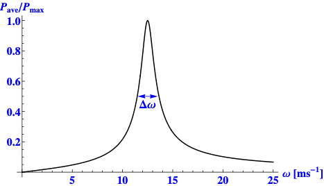
The power resonance curve is a plot of power versus frequency. We will do the calculations in \(\omega\) rather than \(f\) to simplify writing. The average power \(P\) as a function of \(\omega\) for a series \(RLC\) circuit is given by
\begin{equation*}
P(\omega) = \dfrac{V_0^2 R}{2\left[R^2 + \left(\omega L - 1/\omega C \right)^2 \right]}.\ \ \ \ (1)
\end{equation*}
The maximum of this function occurs at \(\omega = 1/\sqrt{LC}\text{.}\) Setting this for \(\omega\) in this equation gives the value at maximum.
Let us illustrate the power curve by a figure of \(P\) vs \(\omega\text{.}\) I have used \(R = 5\:\Omega\text{,}\)\(L = 3\) mH, \(C = 1.6\:\mu\)F, and \(V_0 = 10\) V. The values have been picked for illustrative purpose only.
To find the width of the curve we set \(P(\omega)\) in (1) to \(\dfrac{1}{2} P_{\textrm{max}}\text{.}\) This give the following equation for \(\omega\text{.}\)
\begin{equation*}
\left(\omega L - 1/\omega C \right)^2 = R^2.
\end{equation*}
This equation is an polynomial equation of fourth power in \(\omega\text{.}\) Keeping only the positive solutions for \(\omega\) we get
21.Adjusting Resistance to Sharpen the Current Resonance Curve.
A series RLC circuit with \(R = 4\, \text{k}\Omega\text{,}\)\(C = 0.3\, \text{pF}\text{,}\) and \(H = 2\, \text{pH}\) is driven at the frequency of the current resonance. How should the resistance in the circuit be adjusted so as to sharpen the width of the current resonance to half the original width?
Let \(R\) be adjusted from \(R_1 = 4\:\textrm{k}\Omega\) to \(R_{2}\) keeping everything else same so that \(\Delta \omega\) becomes half as much. This requirement on (1) gives
\begin{equation*}
R_2 = \frac{1}{2} R = 2\:\textrm{k}\Omega.
\end{equation*}
22.Tuning an AM-Radio by Varying Resistance and Capacitance.
A series RLC circuit for tuning into an AM radio station. The circuit has a variable resistor of resistance between \(2\, \Omega\) and \(2000\, \Omega\text{,}\) a variable capacitor whose capacitance could be varied between \(0.1\, \text{pF}\) and \(100\, \text{pF}\text{,}\) and a fixed inductance of \(4\, \text{pH}\text{.}\) What settings of the resistor and capacitor would you need so that the circuit would resonate at (i.e. tunes into) a \(450\, \text{kHz}\) signal?
The tuning condition itself does not put restriction on \(R\text{.}\) But, we would need to watch out for the width of the peak so as to stay away from other frequencies being broadcast. If we knew the width of the peak to look out for, we would use choose \(R\) according to the width \(R/L\) of the peak desired.
(a) In the series RLC circuit connected to a sinusoidally varying EMF source, find the amplitude of the induced EMF as a function of time. (b) What is the resonance frequency of the induced EMF?
(a) In the series \(RLC\) circuit connected to a sinusoidally varying EMF source, find the amplitude of the voltage \(V_C\) across the capacitor as a function of time.
(c) Using results of the problem Exercise 40.6.23, find the frequency at which the magnitude of \(V_C\) would equal the magnitude of the induced EMF. What is the significance of this frequency?