Example 34.30. Current, Voltage, and Power in Resistors in Series Circuit.
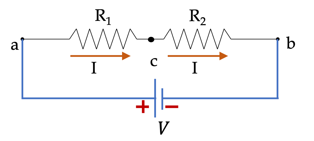
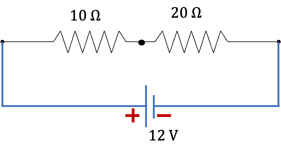
The circuit in Figure 34.31 shows two resitors in series with a voltage source.
Answer.
Solution 1. (a)
Solution 2. (b)
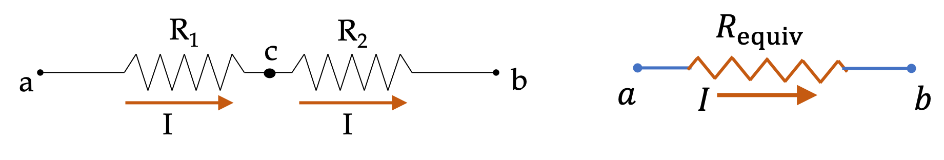
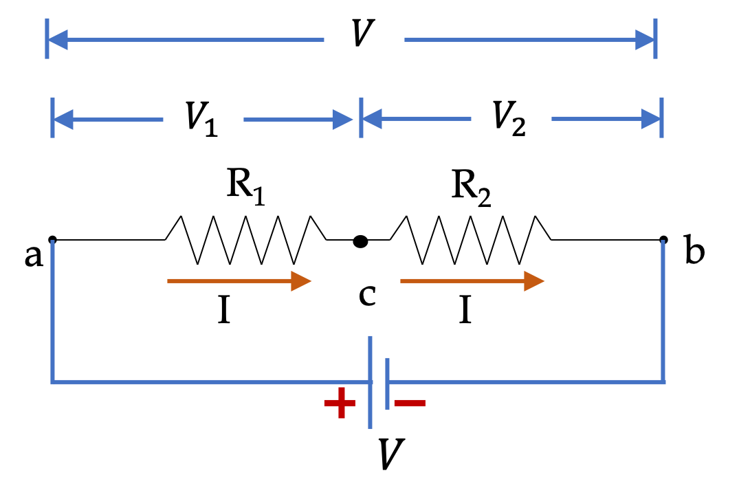
Same current \(I\) flows through both resitors. Applying Ohm’s law on each resitor will give us the potential drops across each of the resitors.
\begin{align*}
V_1 \amp = I_1R_1 = IR_1 = 0.4\text{ A} \times 10\ \Omega = 4\text{ V},\\
V_2 \amp = I_2R_2 = IR_2 = 0.4\text{ A} \times 20\ \Omega = 8\text{ V}.
\end{align*}
Solution 3. (c)
Solution 4. (d)
Energy conservation means the energy lost to the resitors must be suplied by the voltage source. Therefore, the net power of the source must be
\begin{equation*}
P_\text{source} = P_1 + P_2 = 4.8\text{ W}.
\end{equation*}
Therefore energy supplied in \(10\text{ minutes}\) will be
\begin{equation*}
E = P_\text{source}\Delta t = 4.8\text{ W} \times 600\text{ s} = 2,880\text{ J}.
\end{equation*}